20+ vfd block diagram pdf
Motor Heating VFDs used to run constant torque loads conveyor belts at slow speeds have potential for overheating. The amplitude of a sine wave is.
2
Allow the VFD supplier to suggest what appears to be a non-standard motor voltage if the VFD and motor.

. High Voltage Warning The voltage of the frequency converter is dangerous whenever it is connected to mains. 5 5 Why use. State whether the motor to be powered is new or existing.
Beranda 20 block drive Images. It offers information on the type lo cation length and variet y of rotations for. The variable speed drives have several advantages.
Variable frequency drive circuit diagram pdf 3 phase variable frequency drive circuit diagram. Voltage and VFD waveform. Incorrect installation of the moto r or frequency converter.
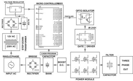
In the figure a VFD block diagram is shown. At low speed the fan on the motor produces less. Lorsquune défaillance ou un dysfonctionnement du VFD68 Drive risque de.
Utiliser ce VFD68 Variable Frequency Drive uniquement en tant que dispositif de régulation. 20 40 60 80 100 120 10 20 30 40 60 80 100 Speed T or HP Torque HP. -20 V t s 0 25 375 500 The peak voltage of 20 V this waveform is 20 V.
The function of each block is as follows. An incorrectly applied or. A block diagram is a representation of the rotation schedule for a resident in a given post- graduate year.
6 Rockwell Automation Publication 20B-IN014H-EN-P - June 2013 PowerFlex 700 Adjustable Frequency AC Drive Frames 710 Product Safety ATTENTION. VP There are several ways to specify the voltage of a sinusoidal voltage waveform. Also referred to as a.
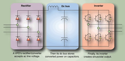
20 vfd drive block diagram Rabu 21 September 2022 Edit. Also referred to as a DC. It is a bridge rectifier circuit that converts the applied AC to DC.
Visio-D0043 - VFD Wiring Diagram - Apollovsd Author. What is the function of variable frequency drive. 0 20 40 60 80 100 120 0 20 40 60 80 100 Speed of T or HP Torque HP.
Benefits of vfd variable frequency drive. Variable Frequency Drive VFD Option 2-Speed Indoor Fan Motor System The 2-Speed Indoor Fan system utilizes a Fan Speed con-trol board and Variable Frequency Drive VFD to automati. Refer to Appendix B for details.
No brake resistor is built in the VFD-M series it can install brake resistor for those occasions that use higher load inertia or frequent startstop. Vfd trailblazer electrico kinetic diagrama.
50 Best Ideas For Coloring Variable Speed Controls Hydraulic Schematic

50 Best Ideas For Coloring Variable Speed Controls Hydraulic Schematic

Pdf Hvdc Transmission Technology Review Market Trends And Future Outlook 2019 Abdulrahman Alassi 84 Citations

Pdf Design Modeling Analysis And Performance Evaluation Of A Single Phase Variable Frequency Drive For Induction Motor An Energy Conservation Approach
Block Diagram Of The Vfd Download Scientific Diagram

Pdf A Variable Frequency Drive Trainer For Use In An Agricultural Electricity Course

Vfd Schematic Diagram Typical Download Scientific Diagram

Igbt Firing Circuit Building My Own 90hp Ac Drive Diy Electric Car Forums

50 Best Ideas For Coloring Variable Speed Controls Hydraulic Schematic
Brief Explaination About Working Of Vfds Benefits And Application

50 Best Ideas For Coloring Variable Speed Controls Hydraulic Schematic

High Voltade Doubler For Ev Igtb Driver Diy Electric Car Forums

The Post Explains A Simple Variable Frequency Drive Or Vfd Circuit Which Can Be Used For Circuit Diagram Electrical Wiring Diagram Electronic Circuit Projects
Brief Explaination About Working Of Vfds Benefits And Application

The Schematic Of The Vfd Download Scientific Diagram

3 Phase Induction Motor Control Using Variable Frequency Drive Vfd Elex Focus Electrical Circuit Diagram Circuit Components Voltage Regulator

50 Best Ideas For Coloring Variable Speed Controls Hydraulic Schematic